Roller Barrier Installation Guide
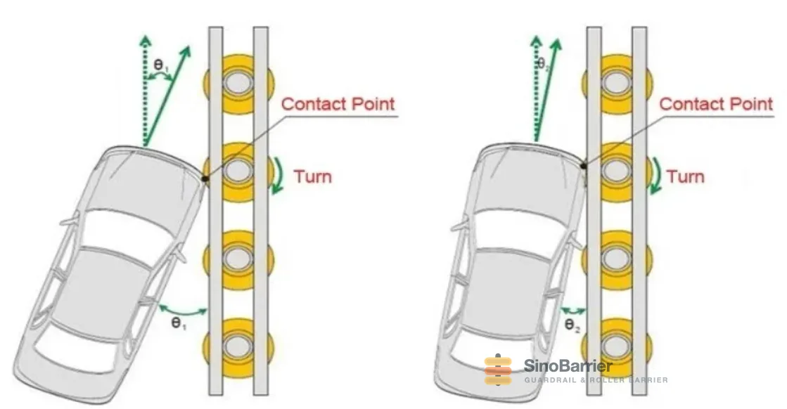
Short answer: a roller barrier is installed in six stages — set out the line, prepare the foundations, set the posts, mount the rollers, align the run, and verify tolerances. The system only redirects vehicles if every roller spins freely and the rows sit at a common height, so the acceptance checks at the end are not paperwork — they are the working principle. Every SinoBarrier order ships with setting-out drawings, foundation details and a bill of materials; this guide walks the sequence and the checks that make the difference on site.
Before you start: the documents that should be on site
Installation quality is decided before the first post hole. Every order ships with three documents that the crew needs in hand:
- Setting-out drawing — post positions against the alignment, with start and end treatments located
- Foundation detail — foundation size and concrete class per ground condition, or the driven-post specification where ground allows
- Bill of materials — rollers, posts, axles, fixings per metre, so site inventory can be checked against the delivery
If any of the three is missing for your project, request it before installation begins — replacements are cheap before concrete, expensive after.
The installation sequence
- Set out the line. Mark post positions from the setting-out drawing with a string line for the full run. Check the run against the alignment — curves in particular need the positions surveyed, not estimated, because the roller rows must follow the geometry smoothly.
- Prepare the foundations. Excavate or auger to the foundation detail and cast the concrete, or drive posts where the ground specification allows. Foundation quality decides how the system behaves in a crash; treat the detail as a specification, not a suggestion.
- Set the posts. Position each post plumb and at the specified height before the concrete takes its final set. Post height tolerance controls the roller rows; a post set low drops its roller out of the guiding surface.
- Mount the rollers. Fit each roller drum on its axle with the supplied fixings, then spin-test by hand. Every roller must rotate freely — a seized drum is a rigid point and is rejected at acceptance, not patched later.
- Align the run. Sight along the full run: the roller rows must form one continuous guiding surface. Correct any roller that sits high, low or twisted before the sign-off survey.
- Verify and sign off. Walk the acceptance checklist (below), record the measurements, and hand over with the checklist attached.
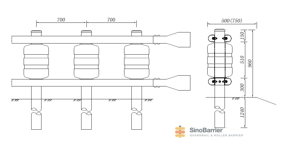
The tolerance checks that matter
| Check | Why it matters | Method |
|---|---|---|
| Post spacing | Spacing beyond drawing tolerance changes system behaviour in a crash | Tape or survey against the setting-out drawing |
| Mounting height | Rows at differing heights break the continuous guiding surface | Level check roller-centre heights, typically 700–900 mm |
| Free rotation | A seized roller is a rigid contact point — the mechanism’s core requirement | Hand-spin every roller; reject and free any that bind |
| Post plumb | Out-of-plumb posts preload the frame and skew the roller rows | Spirit level both axes on every post |
| Fixing torque | Loose axles develop play; overtightened axles bind | Torque wrench to the detail drawing value |
Common installation mistakes — and what they cost later
- Skipping the spin test. A drum blocked by packing debris or a overtightened axle passes visual inspection and fails at the first impact. Hand-spin every roller, every time.
- Estimating curve geometry. On curves, post positions from “eyeball plus tape” produce a wavy roller line — survey the positions.
- Correcting height after the concrete sets. A post set low cannot be raised later; the roller drops out of alignment. Set and check heights in the wet concrete window.
- Mixing roller diameters on one run. 350 mm and 400 mm drums must never alternate — the rows stop reading as one surface. Check deliveries against the BOQ.
Post-impact inspection and routine maintenance
After any impact, inspect the contacted section: post plumb, foundation condition, axle straightness and free rotation of every drum in the affected length. Replace only the units that fail the checks — the modular design means replacement scope is typically a handful of rollers and posts, not a rebuild. Routine maintenance is periodic: spin-test sample rollers, torque-check fixings on exposed sections, and wash drums where dust or salt accumulates. The system’s engineering basis is on the rolling barrier system page and the mechanism behind the checks is explained in how a roller barrier works.
The full specification sheets are on the downloads page, or send your drawing and we return a shop drawing with spacing and mounting details per your alignment.
FAQ
Can a roller barrier be installed on an existing road?
Yes. The system installs on existing verges and medians with either cast foundations or driven posts, depending on ground condition. The setting-out drawing adapts to the existing alignment, and installation can proceed in sections without closing the whole road.
Are the posts set in concrete or driven?
Both methods are supported. Cast concrete foundations are the default where the foundation detail requires them; driven posts are used where ground conditions allow and the project permits. The foundation detail shipped with the order names the method per ground class.
How long does it take to install 100 metres of roller barrier?
With a small crew, an auger and ready-mix concrete, a 100 m run is typically installed in two to three working days including foundation curing time — the roller mounting itself is fast once the posts are set and checked. Actual duration depends on ground conditions and site access.
What acceptance checks are done at handover?
Five checks: post spacing against the drawing, roller-centre mounting height, free rotation of every drum, post plumb on both axes, and fixing torque. The checklist is recorded and attached to the handover documents — a roller that does not spin freely is rejected at acceptance.
Precisa especificar este produto para um projeto em andamento?
Solicite uma cotação